.
Why do we need to take the effort to measure these voltages?
First of all, we can verify if all the resistors are soldered correctly.
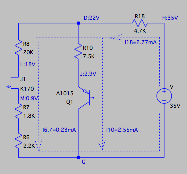
Let us look at the DC circuit for the FET K170. If R8, R7 and R6 are correctly solderred to the right spots, the DC currents flowing through these resistors should be about the same, because they are connected in series. Let us calculate these currents using the Ohm's law.
The DC current through R8 can be calculated as
I8 = (VD - VL) / R8 = (22 - 18) / 20K = 0.2mA
Similarly, the DC current through R7 and R6 can be calculated as
I7,6 = (VM - 0) / (R7 + R6) = 0.9 / (1.8K + 2.2K) = 0.23mA
We can see that I8, and I27,6 are indeed in the same range! They are not exactly the same because each resistor's resistance is not exactly the same as the value indicated. There are always some allowances.
Now, let us look at the DC circuit for the transistor A1015. The DC current flowing through R10 is
I10 = (VD - VJ) / R10 = (22 - 2.9) / 7.5 = 2.55mA
From the circuit, we can see that the sum of the current I8 and I10 should be equal to the current through R18. Let us check if it is valid.
I8 + I10 = 0.2 + 2.5 = 2.7mA
I18 = (VH - VD) / R18 = ( 35 - 22) / 4.7K = 2.77mA
If we found I8 is different from I6,7, or I18 is different from the sum of I8 and I10, we need to check if all these resistors are soldered correctly.
Secondly, we can see if the FET and the transistor are working on a good DC operating point.
To determine strictly if an FET/transistor is working on an optimal DC working point is complicated. But we can judge it roughly by looking at the DC voltages at the FET's Source-Drain-Gate or transistor's emitter-Collector/Base.
The voltage at the source of K170 is 0.9V, and voltage at the gate is, by using Ohm's law again
I6,7 * R6 = 0.23mA * 2.2K = 0.51V.
The negative bias of 0.51-0.9=-0.39V is applied to the G-S junction of K170. In practice, the amplitude of the sound signal from the capsule will be below 100mV (0.1V), so the bias is good.
The voltage at the drain of K170 is 18V when no sound input signal applied to the gate. If the gain of the stage with K170 is 10, then the maximum amplitude of the output sound signal at the drain of K170 will be 1V, which will cause the DC voltage at the drain varying between 17 to 19V. We can see the FET is working on a good DC operating point.
For the transistor A1015, which is a source follower and does not offer any gain to the signal, but acts as an impedance converter. For an input sound signal with an amplitude of 1V, the voltage at A1015's emitter will vary between 1.9 to 3.9V. We can see that A1015 is also working on a good DC operating point.