.
Why do we need to take the effort to measure these voltages? What can we do with these values?
First of all, we can verify if all the resistors are soldered correctly.
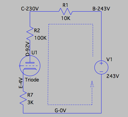
Let us apply the Ohm's law to the circuit shown on the left. We can see from the diagram that a single DC current flows through the whole circuit. That means, the DC currents that flow through each component should be in the same value. Let us check if this is right.
The DC current through R1 can be calculated as, based on Ohm's law,
I1= V / R1 = (243 - 230) / 10K = 1.3 mA
Similarly,
I2 = V / R2 = (230 - 92) / 100K = 1.38 mA
I7 = V / R7 = (4 - 0) / 3K = 1.33 mA
We can see I1, I2, and I7 are indeed in the same range! They are not exactly the same because each resistor's resistance is allowed to vary within a given percentage range.
Secondly, if something is wrong, we will know.
Suppose that if we accidentally swapped R1 with R2, what will happen? Of course, we will not get the same voltages for C, D and E a shown before. But if we calculate I1, I2, and I7, we will find I2 will be 10 times of I1.
Suppose that if all the resistors are in the right spots, but the tube is simply not working. This could happen if the small tube PCB is not well soldered to the main PCB, or when the filament is broken. In the case, we the voltages at C and D will be very close to the voltage at B, and the voltage at E will be almost zero.
Thirdly, we can see if the tube is working on a good DC operating point.
To determine if a tube is working on an optimal DC working point is complicated. But we can judge it roughly by looking at the DC voltages at the tube cathode and anode.
The voltage at the cathode is 4V when there is no sound signal applied to the grid of the tube. Because the voltage at the grid is zero, the grid DC voltage relative to the cathode, Vgc is -4V. If a sound signal with an amplitude of 1V comes in, the grid voltage Vgc will vary between -3V to -5V, which is in a good range.
If the gain factor of the tube is 20, then the amplitude of the amplified sound signal at the anode will be 20V. The DC voltage at the anode will vary between 72V to 112V. Which is also in a good range.
In practice, the amplitude of the sound signal from the capsule will be below 100mV (0.1V), so the tube is indeed working on a good DC operating point.