Every resistors and capacitors are indicated as R1, R2, ...., and C1, C2, ... in the schematics, and on the PCB, accordingly. It is very important to put them into the right spots. Putting any one of them into a wrong place will consume a lot of time for the trouble shooting.
To figure out which resistor and capacitor is which, you need to know how to read the values marked on them. For capacitors, the values are marked directly. To see the annotation rules and the list of the capacitors used in the kit, click the link:
How to read the value on a capacitor
But for resistors, the numbers are sometimes coded by colors. To see the annotation rules and the list of the resistors used in the kit, click the link:
How to read the value on a resistor
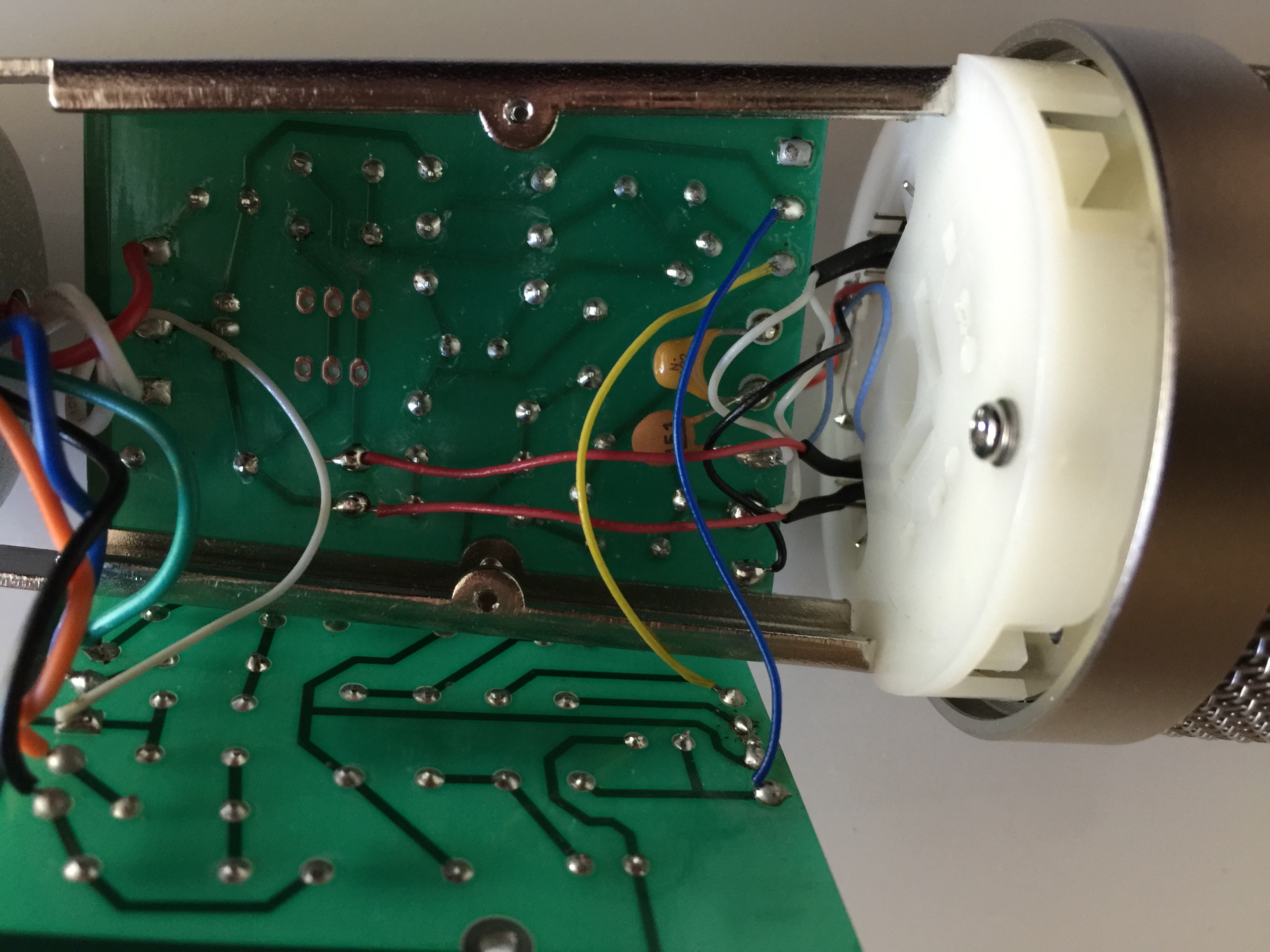
The PCBs with the components soldered on, is shown in the following picture. Note that C1 and C2 are soldered on the back of the PCB.
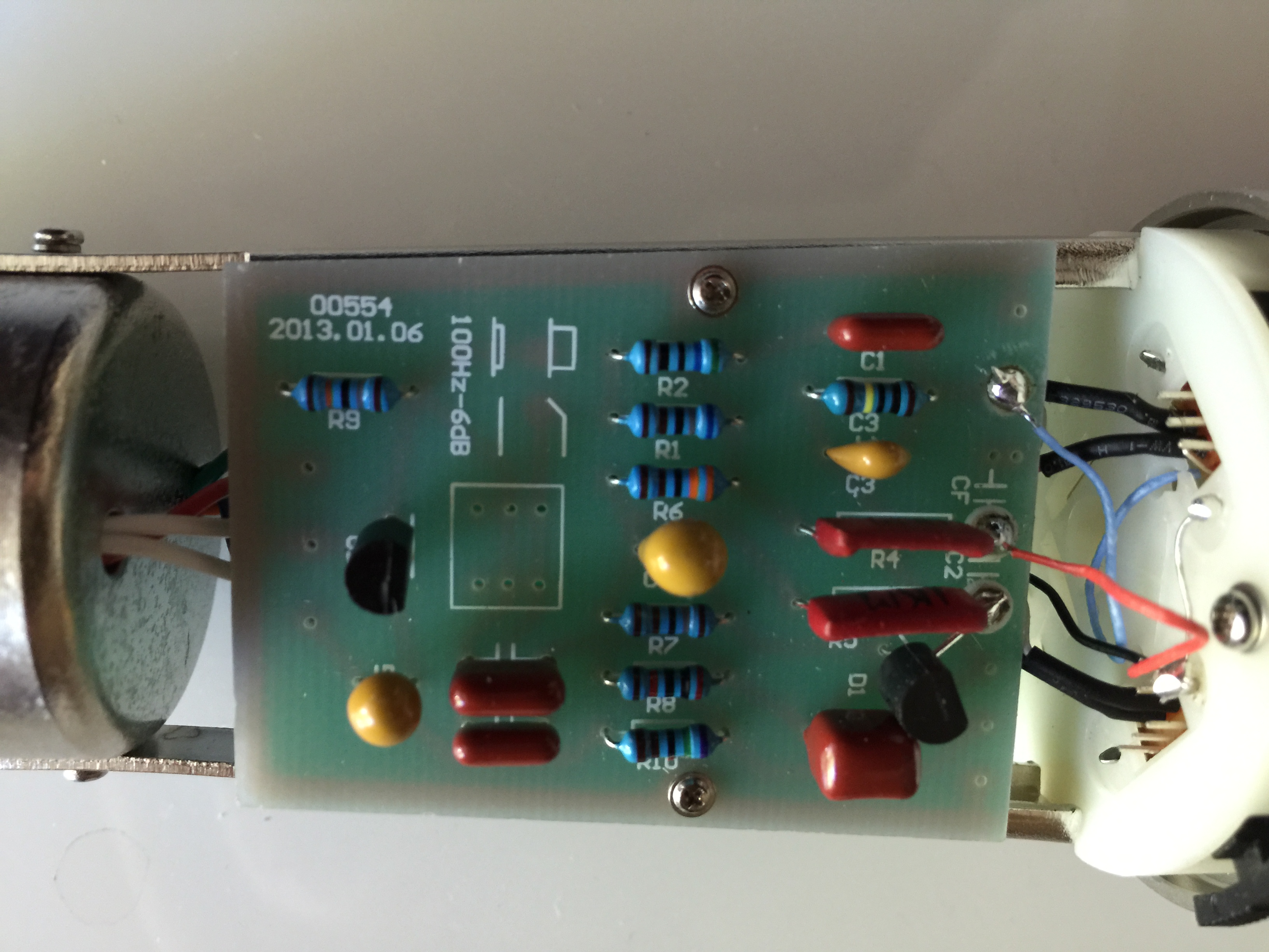 |
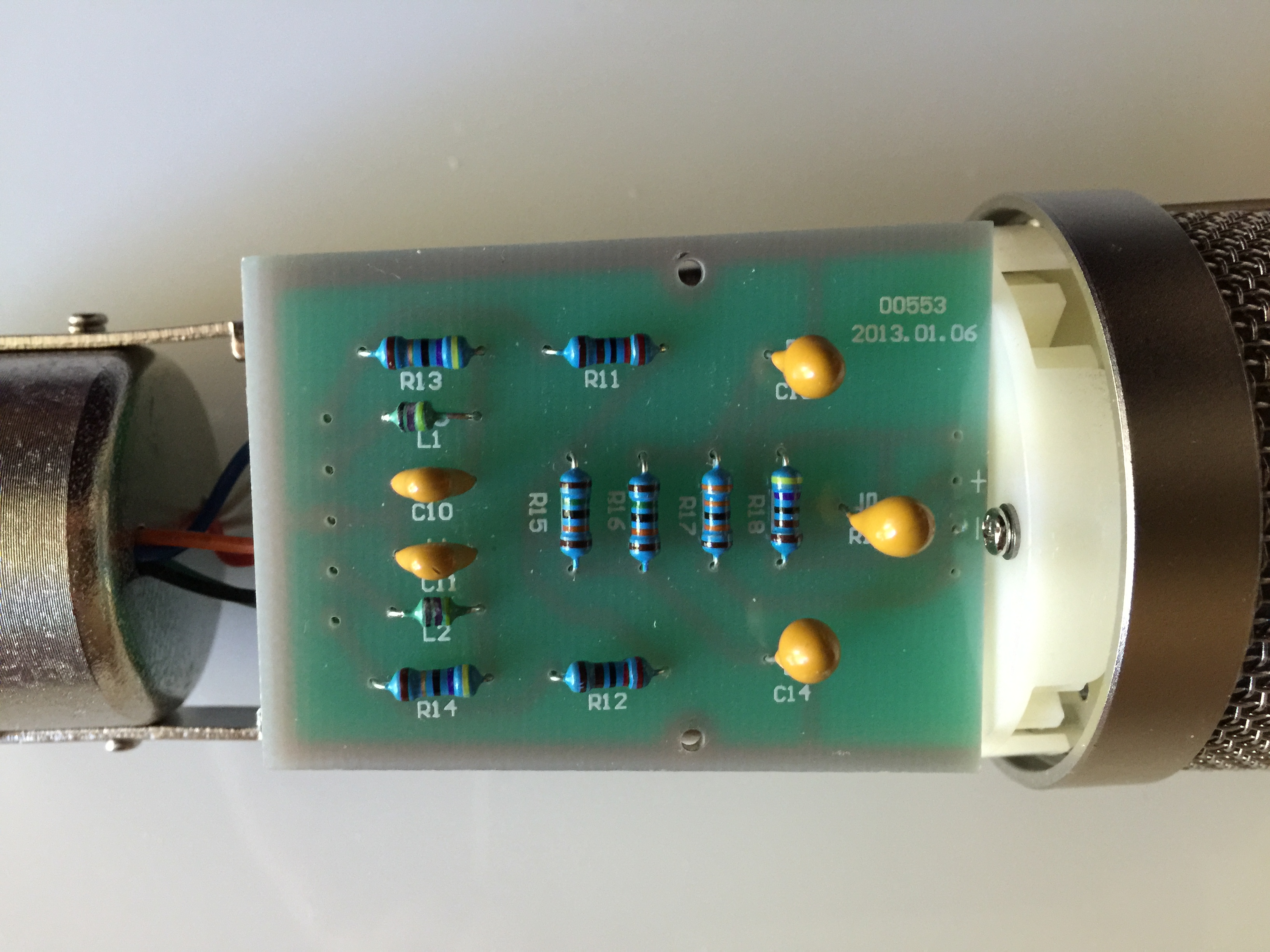 |
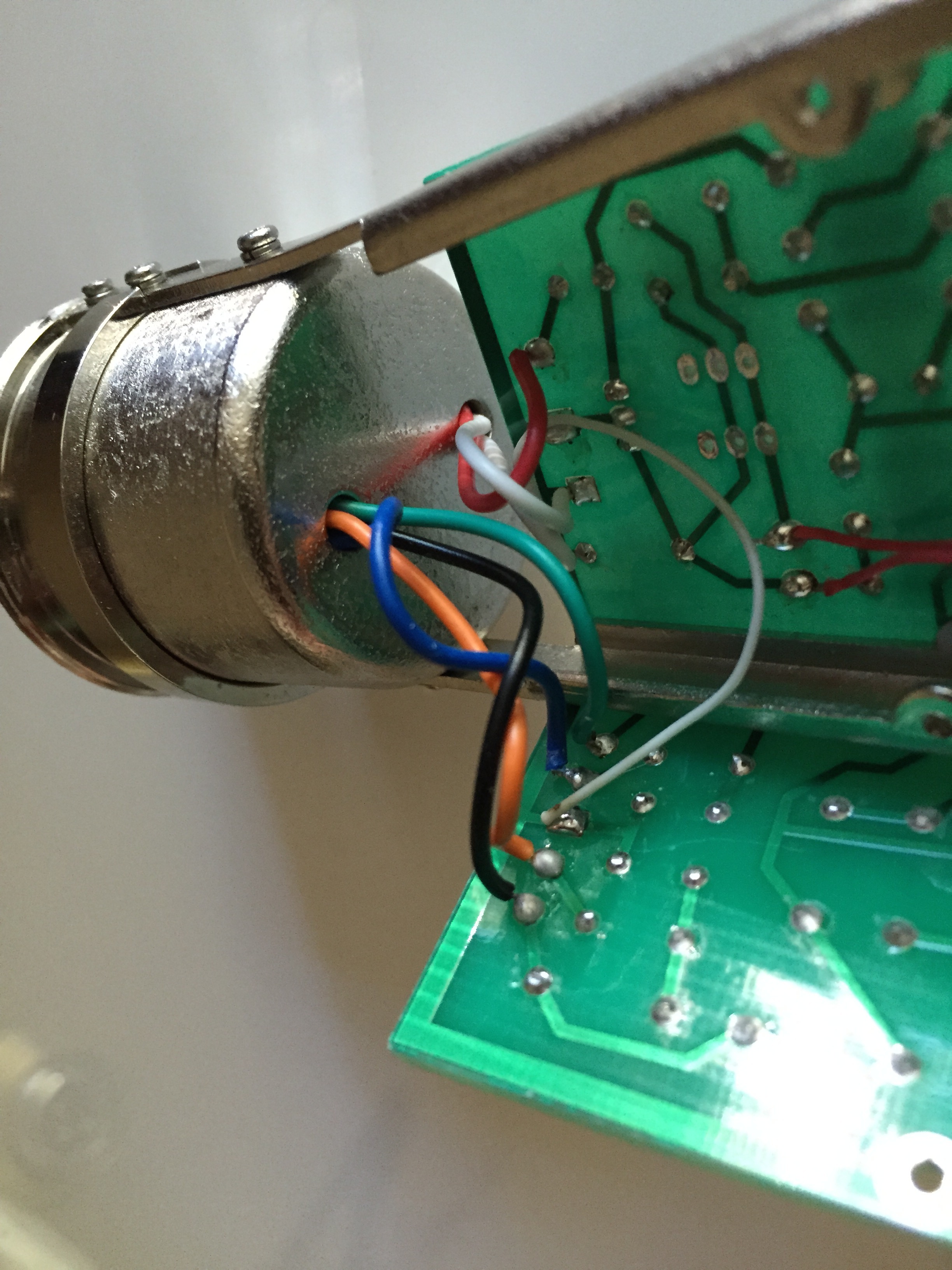
Now you need to solder the seven wires from the microphone base onto the PCB: three from the XLR connector, two from the primary and two from the secondary coils of the output transformer. The first thing is to determine which one is which. Although the wires are colored, but following the steps in the link below will let you identify each wire for sure.
How to identify the seven wires comming out of the base
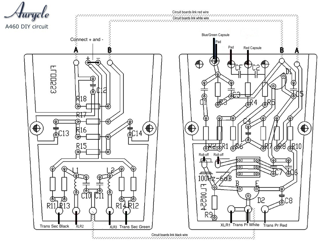
The connections of the three wires from XLR and four wires from the transformer, the jump between the points + and - on the PCB, and the connections of three wires between two PCBs are shown in the following pictures.
Step 3: Connect the wires from the capsule and two switches to the PCB
Then, you need to connect the wires from the capsule and the two switches to the PCBs. Please refer to the picture below.
The picture shows which switch is connected to what points on the PCB. Please connect the wires correctly. Do not rely on the colors of the wires from two switches, since they might vary. But the two wires from the SAME switch are allowed to be swapped.
Note that you also need to connect the two PCB with two of the three wires supplied.
If everything is going on correctly, you can hook up the microphone, and enjoy recording your song or your music. When something goes wrong, you need to figure out what it is and fix it. You need to go through the following steps.
Even if your microphone is working properly, you can still go through these steps, because by doing so, you will learn how and why a microphone works, and the physics laws behind all of these. Gaining these knowledges, you will become a designer from an assembler, and you can modify your microphone to meet your own specific needs.
The circuit in the main PCB is a pre-amplifier for the sound signal from the capsule. The center piece of the amplifier is the FET K170. The FET takes in a sound signal from the capsule as input, and output an amplified signal to the second stage. The second stage, with a transistor A1015, does not provide any gain to the signal, and it works as an impedance convertor. In order to amplify the signal, or to convert the impedance, the K170 and A1015 have to be supplied with DC voltages to its drain, source and gate, or, collector, emitter, and base, which is often referred as the DC operating point.
The circuit for the FET mic DIY kit has been carefully designed to ensure the K170 and A1015 are working on an optimal DC operating point. To see if your circuit is actually doing so, you need to measure the DC voltages at several points on the PCBs.
Normally, you need to measure the DC voltages of the points on the PCBs indicated in the following picture.
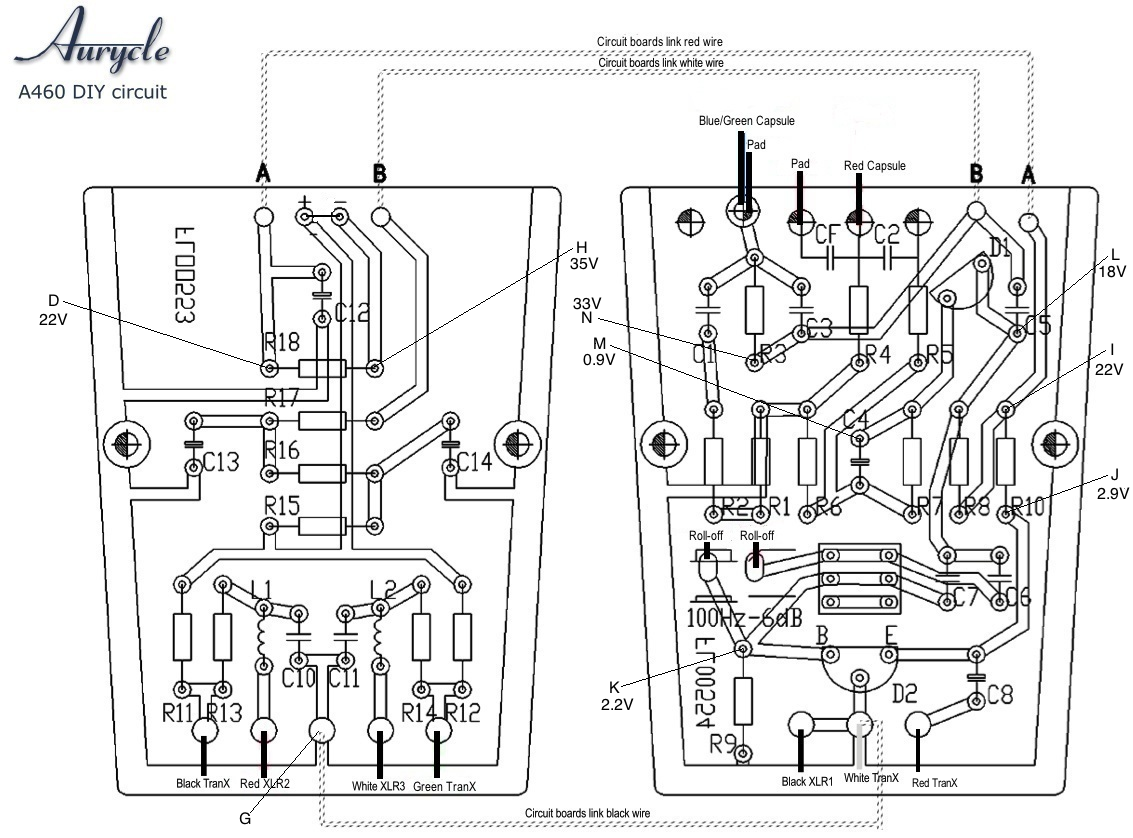
In the above picture, G is the ground. All the DC voltages are referred to this point. The point H connects to the phantom power through the pin 2 and 3 of the 3-pin connector, which supplies DC voltage to the circuit. The normal value should be around 35V. The DC voltage of the point D and A should be around 22V.
The point L is the drain of the FET, and the DC voltage should be around 18V. The point M is the source of the FET, and the DC voltage should be around 0.9V.
The second stage of the pre-amplifier circuit is a source follower. The point J and K are the emitter and base of the transistor, respectively, and the DC voltages should be around 2.9V and 2.2V. To see why all these DC voltages take these values, click the link
Why do the DC voltages take these values?
The fact that the FET and transistor are working on a good DC operating point, does not mean it can amplify sound signals properly. If you get all the DC values in a right range, but you still cannot get good sound from the microphone, you need to go through this step.
The sound signals are AC signals, they have there own input and output paths. To check all these audio paths, special instruments are needed, like audio signal generator, and a device which can display and measure audio signals. We are not going into this field here now. We will post some other web pages for this subject later, for the readers who want to lear those advanced techniques.
The simplest way to do it, without the help of special devices, is to check if all the two wires from the capsule, and the four wires from the transformer are correctly connected to the PCBs, because the capsule and the transformer are in the audio AC paths. You also need to check if the three capacitors, C2, C4, C7, and C8 are correctly placed on the PCB, because they are also in the audio paths.