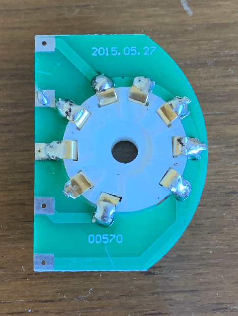
1) Insert the tube socket into the tube PCB. The tube socket must be inserted to the tube PCB in the right direction showing in the picture bellow.
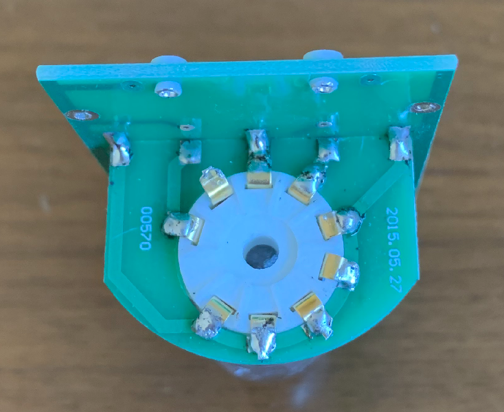
2) Solder all pins of the tube to the tube PCB, except for the pin 2.
3) Solder the tube PCB onto the main PCB. As shown in the following pictures.
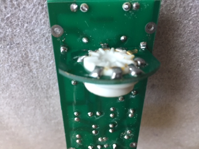
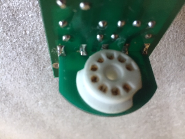
Notes: It is not neccessary to use any wires to bind the tube PCB to the main PCB. Good soldering will provide enough mechanical support to the tube PCB. The soldering should also provide good electrical connections between the two PCBs, which is critical because all pins of the tube are connected to the main PCB through the connections between the two PCBs.
Step 2: Solder the resistors and capacitors into the right spots on the PCB
Every resistors and capacitors are indicated as R1, R2, ...., and C1, C2, ... in the schematics, and on the PCB, accordingly. It is very important to put them into the right spots.
To figure out which resistor and capacitor is which, you need to know how to read the values marked on them. For capacitors, the values are marked directly. To see the annotation rules and the list of the capacitors used in the kit, click the link
How to read the value on a capacitor
But for resistors, the numbers are sometimes coded by colors. To see the annotation rules and the list of the resistors used in the kit, click the link below. Another way is just to directly measure the resistance of the resistors using Ohm-meter.
How to read the value on a resistor
The PCB with the components soldered on is shown on the following picture:

Step 3: Connect the transformer and 7-pin connector to the PCB
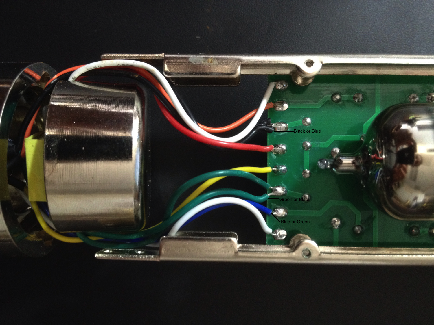
Now you need to solder the 10 wires from the microphone base onto the PCB. This is not an easy job. If you make any wrong connection, the microphone will not work, and in the worst case, the components on the PCB will be damaged.
1) Find the two wires of the primary coil of the transformer. Usually, they are red and white. You need to measure the resistance between the two wires, and it should be around 850 Ohm. If not, you need to find the two wires with this resistance.
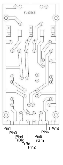
2) Refering the picture below, solder the red and white wires to the points on the PCB marked as 'TrRd' and 'TrWht', respectively.
3) Find the two wires of the secondary coil of the transformer. Usually they are black and green.You need to measure the resistance between the two wires, and it should be around 50 Ohm. If not, you need to find the two wires with this resistance.
4) Solder the black and green wires to the points on the PCB marked as 'TrBlk' and 'TrGrn', respectively.
5) Now there are 6 wires left which are not connected yet. They come from the 6 pins of the 7-pin connector on the bottom of the microphone. Look at the connector carefully and you can see each pin is marked with a number.
6) Find which wire connects to the pin 1. You need to measure the resistance between the pin 1 and every wire of the 6 unconnected wires. The resistance should be zero.
7) Solder this wire, usually it is white, to the point on the PCB marked as 'Pin1'.
8) Find which wire connects to the pin 2 with the same measurement. Solder this wire to the poin on the PCB marked as 'Pin2'.
9) Do the same for pin 3, pin 4, pin 5 and pin6.
Notes:
For the single polar pattrn kit, A5500, there are only 9 wires from the base, because there is no wire connects to the pin 6.
One of finished wiring is shown in the following picture. Do not rely on the colors of the wires. The kit you receive may have different colors for the 10 wires. Please follow strictly the above instructions to do the connection.
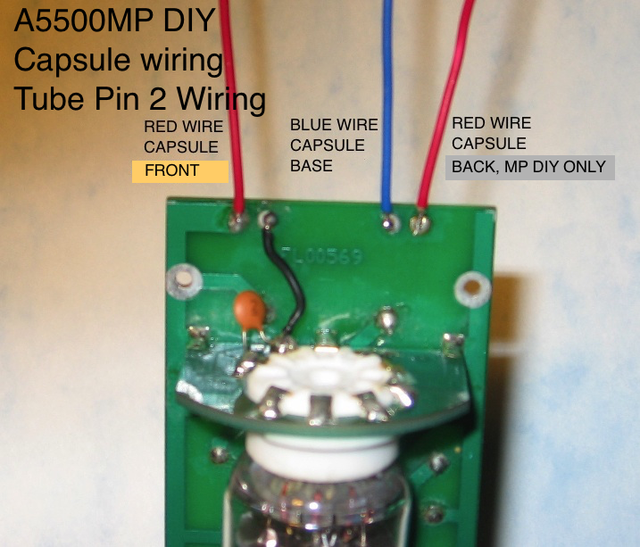
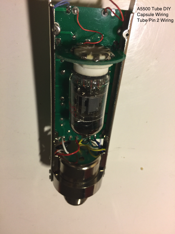
Step 4: Connect the capsule to the PCB
Then, you need to connect the wires from the capsule to the PCB. The wirings are shown in the following picture. Note that only the Tube Mic MP DIY kit has a dual diaphragm and you need to connect the red wire from the back diaphragm to the PCB.
If everything is going on correctly, you can hook up the microphone with the PSU, and enjoy recording your song or your music. When something goes wrong, you need to figure out what it is and fix it. You need to go through the following steps.
Even if your microphone is working properly, you can still go through these steps, because by doing so, you will learn how and why a microphone works, and the physics laws behind all of these. Gaining these knowledges, you will become a designer, rather than only an assembler, so you can modify your microphone to meet your own specific goal.
The circuit in the main PCB is a pre-amplifier for the sound signal from the capsule. The center piece of the amplifier is the tube. The tube takes in a sound signal from the capsule as input, and output an amplified signal to the transformer. In order to amplify the signal, the tube has to be supplied with right DC voltages to its anode and cathode, which is often referred as its DC operating point.
The circuit for the tube mic DIY kit has been carefully designed to ensure the tube is working on an optimal DC operating point. To see if your tube is actually doing so, you need to measure the DC voltages at several points on the PCB.
Normally, you need to measure the DC voltages of the points on the PCB indicated in the following picture.
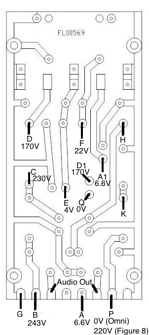
In the above picture, G is the ground. All the DC voltages are referred to this point. The point A connects to the pin 2 of the 7-pin connector, which supplies DC voltage to the filament of the tube. If the tube's filament and the connection to it is good, the DC voltage on it should be about 6.6V. If the filament or the connection to it is broken, the DC voltage on the point A will be around 11V. To see why, and how to fix it, click the link
Why is the filament voltage too high?
The point B connects to the pin 3 of the 7-pin connector, which supplies the tube with the high DC voltage. The normal value should be around 243V. The DC voltage of the point C should be around 230V. The point D is the anode of the tube, and the DC voltage on the anode should be around 92V. The point E is the cathode of the tube, and the DC voltage on it should be around 1.5 to 4V. To see why all these DC voltages take these values, click the link
Why do the DC voltages take these values?
The fact that the tube is working on a good DC operating point, does not mean it can amplify sound signals properly. If you get all the DC values in a right range, but you still cannot get good sound from the microphone, you need to go through this step.
The sound signals are AC signals, they have their own input and output paths. To check all these AC paths, special instruments are needed, like audio signal generator, and a device which can display and measure audio signals. We are not going into this field here now. We will post some other web pages for this subject later, for the readers who want to lear those advanced techniques.
The simplest way to do it, without those special devices, is to check if all the two (for single polar pattern) or three (for multi polar pattern) wires from the capsule, and the four wires from the transformer are correctly connected to the PCB, because the capsule and the transformer are in the audio paths. You also need to check if the three capacitors, C4, C6, and C8 are correctly placed on the PCB, because they are also in the audio paths.